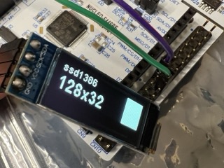
STM32에 SSD1306 OLED 모듈을 연결했습니다.
오픈소스가 많이 있어서 어렵지 않게 동작을 확인해볼 수 있었지만,
쉽게 검색되는 코드를 사용했을때는 글씨가 화면 전체에 제대로 출력되지 않았습니다.
128x32 크기에 맞는 수정을 위한 코드리뷰가 필요했고,
겸사겸사 초기화 코드와 데이터시트를 보며 각 설정의 내용을 살펴보았습니다.
I2C로 연결했기에 https://github.com/4ilo/ssd1306-stm32HAL 를 사용했습니다.
ssd1306_Init()의 코드:
https://github.com/4ilo/ssd1306-stm32HAL/blob/master/lib/ssd1306.c#L23
ssd1306-stm32HAL/lib/ssd1306.c at master · 4ilo/ssd1306-stm32HAL
ssd1306 library for stm32 using hal library. Contribute to 4ilo/ssd1306-stm32HAL development by creating an account on GitHub.
github.com
Set Display ON/OFF (AEh/AFh)
초기화의 처음과 끝은 display on/off 입니다.

WriteCommand(0xAE); // display off
// initialization
WriteCommand(0xAF); // display on
Set Memory Addressing Mode (20h)
Memory addressing mode(0x20)를 Page addressing mode(0x10)로 설정합니다.
Starting RAM access pointer location(0xB0, 0x00, 0x10)을 설정합니다.
* 0xC8은 아래에서 보겠습니다.
WriteCommand(0x20); // Set Memory Addressing Mode
WriteCommand(0x10); // 10,Page Addressing Mode (RESET)
WriteCommand(0xB0); // Set Page Start Address for Page Addressing Mode,0-7
WriteCommand(0xC8); // Set COM Output Scan Direction
WriteCommand(0x00); // Set low column address
WriteCommand(0x10); // Set high column address
starting RAM access pointer location 설정은 아래의 순서대로 합니다.
• Set the page start address of the target display location by command B0h to B7h.
• Set the lower start column address of pointer by command 00h~0Fh.
• Set the upper start column address of pointer by command 10h~1Fh.
각 페이지의 데이터를 적용하는 아래의 코드를 보면 항상 동일한 순서대로 위치를 설정해 줍니다.
void ssd1306_UpdateScreen(I2C_HandleTypeDef *hi2c)
{
    uint8_t i;

    for (i = 0; i < 8; i++) {
        ssd1306_WriteCommand(hi2c, 0xB0 + i); // page start address
        ssd1306_WriteCommand(hi2c, 0x00);     // lower start column address
        ssd1306_WriteCommand(hi2c, 0x10);     // upper start column address

        HAL_I2C_Mem_Write(hi2c, SSD1306_I2C_ADDR, 0x40, 1, &SSD1306_Buffer[SSD1306_WIDTH * i], SSD1306_WIDTH, 100);
    }
}

Set Display Start Line (40h~7Fh)
Display Start Line을 0x40으로 설정합니다.
0 ~ 63 범위의 값을 설정하며 RAM row0은 COM0 부터 row63은 COM63 에 매핑되는 방식입니다.
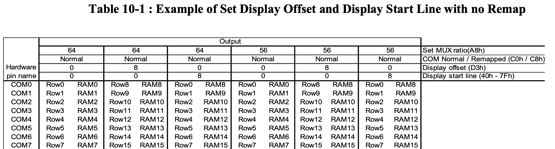

RAM의 데이터가 (a)방식으로 매핑됩니다.
Set Contrast Control for BANK0 (81h)
Contrast Setting(0x81)을 0xFF로 설정합니다.
256 contrast steps from 00h to FFh.
The segment output current increases as the contrast step value increases.
WriteCommand(0x40); // Set start line address
WriteCommand(0x81); // set contrast control register
WriteCommand(0xFF); //
Set Segment Re-map (A0h/A1h)
Segment Re-map을 0xA1로 설정합니다.
This command changes the mapping between the display data column address and the segment driver.
This command only affects subsequent data input. Data already stored in GDDRAM will have no changes.
A0h, X[0]=0b: column address 0 is mapped to SEG0 (RESET)
A1h, X[0]=1b: column address 127 is mapped to SEG0
Set Normal/Inverse Display (A6h/A7h)
Normal Display(0xA6)로 설정합니다.
This command sets the display to be either normal or inverse. In normal display a RAM data of 1 indicates an
“ON” pixel while in inverse display a RAM data of 0 indicates an “ON” pixel.
A6h, X[0]=0b: Normal display (RESET)
0 in RAM: OFF in display panel
1 in RAM: ON in display panel
A7h, X[0]=1b: Inverse display
0 in RAM: ON in display panel
1 in RAM: OFF in display panel
WriteCommand(0xA1); // Set segment re-map 0 to 127
WriteCommand(0xA6); // Set normal display
Set Multiplex Ratio (A8h)
multiplex ratio(0xA8)을 128x32 크기에 맞게 32-1(0x1F)로 설정합니다.
This command switches the default 63 multiplex mode to any multiplex ratio, ranging from 16 to 63.
The output pads COM0~COM63 will be switched to the corresponding COM signal.
WriteCommand(0xA8); // Set multiplex ratio(1 to 64)
WriteCommand(0x1F); // 32 - 1
WriteCommand(hi2c, 0xA4); // 0xa4,Output follows RAM content
WriteCommand(hi2c, 0xD3); // Set display offset
WriteCommand(hi2c, 0x00); // No offset
WriteCommand(hi2c, 0xD5); // Set display clock divide ratio/oscillator frequency
WriteCommand(hi2c, 0xF0); // Set divide ratio
WriteCommand(hi2c, 0xD9); // Set pre-charge period
WriteCommand(hi2c, 0x22);
Entire Display ON (A4h/A5h)
A4h command enable display outputs according to the GDDRAM contents.
Set Display Offset (D3h)
This is a double byte command. The second command specifies the mapping of the display start line to one of
COM0~COM63 (assuming that COM0 is the display start line then the display start line register is equal to 0).

Set Display Clock Divide Ratio/ Oscillator Frequency (D5h)
This command consists of two functions:
• Display Clock Divide Ratio (D)(A[3:0])
Set the divide ratio to generate DCLK (Display Clock) from CLK. The divide ratio is from 1 to 16,
with reset value = 1.
• Oscillator Frequency (A[7:4])
Program the oscillator frequency Fosc that is the source of CLK if CLS pin is pulled high. The 4-bit
value results in 16 different frequency settings available as shown below. The default setting is 1000b.
Set Pre-charge Period (D9h)
This command is used to set the duration of the pre-charge period. The interval is counted in number of DCLK, where RESET equals 2 DCLKs.
WriteCommand(hi2c, 0xDA);   // Set com pins hardware configuration
WriteCommand(hi2c, 0x02);
Set COM Pins Hardware Configuration (DAh)
COM signals pin configuration 을 OLED panel hardware layout에 매칭하는 방식을 설정합니다.
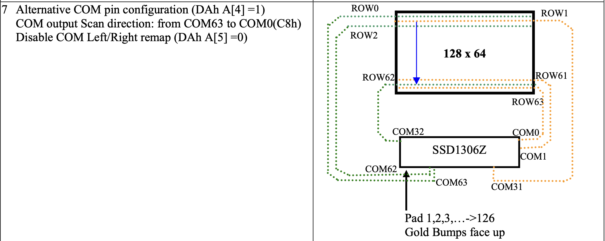
Set COM Output Scan Direction (C0h/C8h)
설정 초반에 scan direction of COM output은 0xC8로 설정했습니다.
C0h, X[3]=0b: normal mode (RESET) Scan from COM0 to COM[N –1]
C8h, X[3]=1b: remapped mode. Scan from COM[N-1] to COM0
Where N is the Multiplex ratio.
WriteCommand(0xDB); // Set vcomh
WriteCommand(0x20); // 0x20,0.77xVcc
WriteCommand(0x8D); // Set DC-DC enable
WriteCommand(0x14);
Set VCOMH Deselect Level (DBh)
This command adjusts the VCOMH regulator output.
Set Charge Pump Setting
A[2] = 0b, Disable charge pump(RESET)
A[2] = 1b, Enable charge pump during display on
Note
(1) The Charge Pump must be enabled by the following command:
8Dh ; Charge Pump Setting
14h ; Enable Charge Pump
AFh; Display ON
https://github.com/4ilo/ssd1306-stm32HAL?tab=readme-ov-file#128x32-example
GitHub - 4ilo/ssd1306-stm32HAL: ssd1306 library for stm32 using hal library
ssd1306 library for stm32 using hal library. Contribute to 4ilo/ssd1306-stm32HAL development by creating an account on GitHub.
github.com
'MCU' 카테고리의 다른 글
| STM32-CAN-Raspberry Pi (0) | 2025.04.07 |
|---|---|
| DHT22 온습도 센서 (0) | 2025.03.23 |
| STM32 clock (0) | 2025.01.23 |
| FreeRTOS - STM32F4 포팅 정보 확인 (0) | 2025.01.14 |
| FreeRTOS 와 Zephyr 비교 (0) | 2025.01.13 |


